Build your own MacClip Jr!
Before following this guide, I recommend reading about ‘040 Overclocking
This guide provides a non-invasive, reversible, and optionally no-solder method to install Kero’s Spicy O’ Clock inspired by Marc Schrier’s “Method 3”, which you can read about in the overclocking guide above. This provides the ultimate ‘040 Mac overclocking experience: a Mac which you can return to stock in seconds using easily purchasable modern parts.
To do this you’ll need a few things:
- A quality SOIC test clip supporting 0.34in/300mil/8.65mm chips with at least 10 pins, this includes:
- Pomona
5251 - 3M
923660-16 - 3M
923655-16 - Pomona
5252 - 3M
923660-18 - 3M
923665-18 - Of these, I recommend the Pomona
5251as it offers the smallest overall size. It’s readily availible at typical suppliers like Digikey and Mouser. - You can find super cheap generic clones on Amazon and Aliexpress, but these are really hit or miss. You want the clip to have great contact and stay seated, it’s worth a few extra bucks.
- Pomona
- A Spicy O’ Clock.
- Electrical tape.
- Double stick tape.
- If you want a no solder solution: 3 jumper wires with female-to-female Dupont connectors. One with female-to-male.
- Optional: upgraded ‘040 compatible heat sink and fan assembly.
Steps
Note: if you prefer a soldered installation, replace each jumper connection with a solder attachment instead, excepting the male lead connected to the NuBus slot.
- Completely read through the Spicy O’ Clock manual. It’s important to understand the basics of the unit. We will be ignoring the installation instructions in favor of our own procedure.
- Power off your machine.
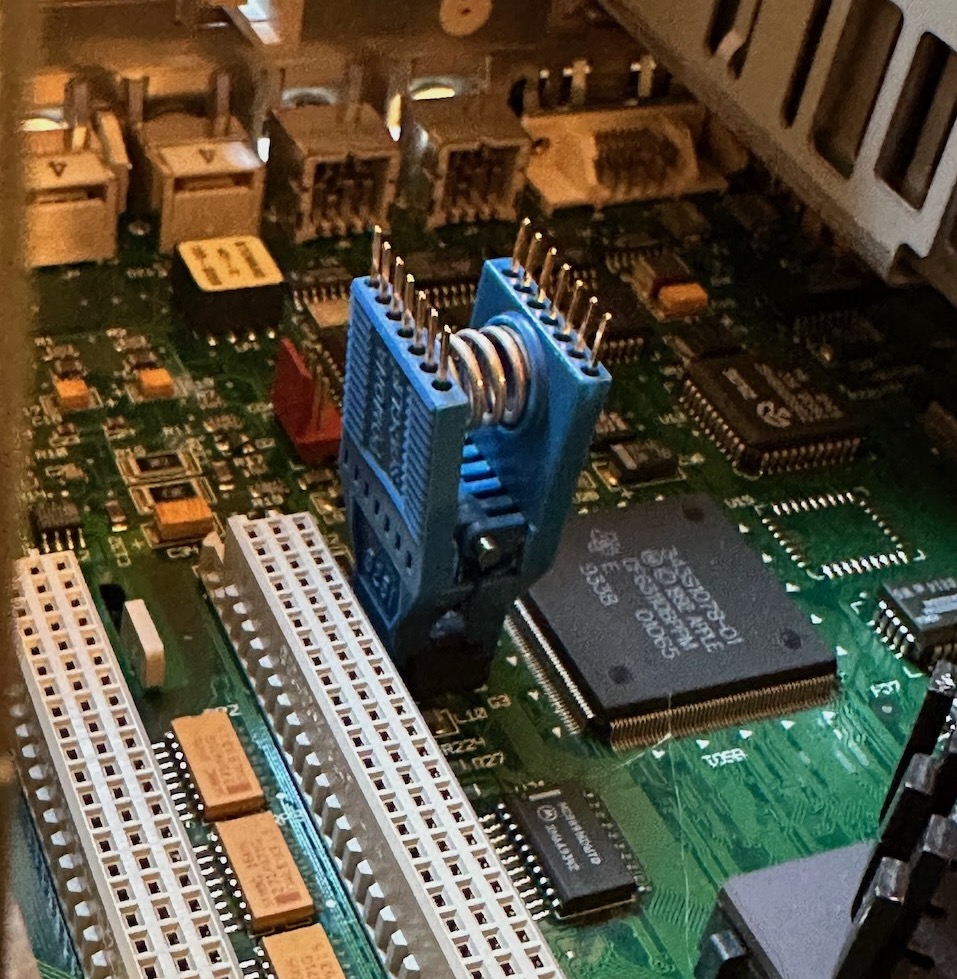
- First we’re going to attach the clip:
- Locate the clock chip on your board. For a Wombat board (C650, Q650, Q800) this will be labeled
G3, and is located next to the rightmost NuBus slot when looking from the front of the case. - Place the SOIC test clip onto the chip. You must align it correctly. If you have a > 10 lead clip, it may hang off the edges, which is fine as long as the clip is making contact with all 4 leads on the oscillator.
- Turn the machine on.
- Determine which pin has the 5v rail to confirm the chip alignment. On a Wombat board it should be near the bottom left of the clip, when looking from the front of the case. To determine this, use a multimeter in DC voltage mode with one lead touching the case (ground) and one lead touching each of the pins on the top of the clip, one by one. When it reads ~5v, you have located the pin.
- Mark this pin to orient yourself going forward.
- Turn the machine off again.
- Locate the clock chip on your board. For a Wombat board (C650, Q650, Q800) this will be labeled
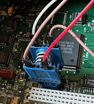
- Next, we need to attach the leads to the clip:
- Connect a female-to-female jumper cable to the 5v Vcc pin.
- Move 4 pins up on this row. This is the oscillator output pin. Connect another female-to-female jumper. For clarity, this means there will be two jumpers on this row, with 3 unpopulated pins between them.
- Now move to the other row of pins on the clip.
- Find the pin across from the oscillator output pin, this is the ground pin. Attach a female-to-female jumper.
- Find the pin across from the 5v Vcc pin, this is the Output Enable (OE) pin. Attach a female-to-male jumper.
- Now we must disable the onboard oscillator. This is completely reversable, by grounding the Output Enable pin the onboard oscillator temporarily disables itself. To do this we can use the NuBus slot’s ground pins.
- Locate the nearest unused NuBus slot. If all NuBus slots are populated, you’ll need to find another source of ground on the logic board. These instructions assume you are using the NuBus slot.
- The NuBus slot’s middle row, row B, has ground on the center 11 pins. This makes it very easy to find a ground. Count 12 pins from either end and select a pin to connect, but do not connect it yet.
- Turn the machine on.
- It is extremely critical you connect this to the right pins. 12v is also present on the NuBus slot which can potentially destroy your oscillator or logic board. To do this, once again use a multimeter in DC voltage mode, with one lead connected to the case (ground). Connect the other to the pin you have selected. It should read very close to 0v.
- Turn the machine off.
- Connect the male end of the jumper from the Output Enable pin to the pin on the NuBus slot you have selected. At this point the onboard oscillator is disabled and your machine will no longer boot when powered on. We will then enable the new oscillator on the Spicy O’ Clock in the next steps.
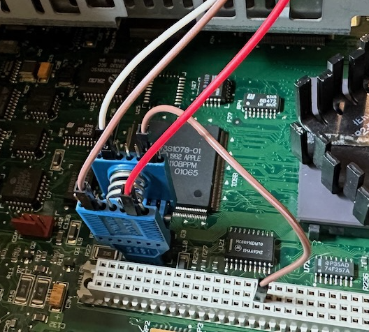
- Now we can connect the other pins to the Spicy to enable it:
- Connect the other end of the jumper on the ground pin to your Spicy O’ Clock’s ground pin. This is the rightmost pin when the Spicy is facing up.
- Connect the other end of the jumper on the oscillator output pin to your Spicy O’ Clock’s out pin. This is the leftmost pin when the Spicy is facing up.
- Connect the other end of the jumper on the 5v Vcc pin to your Spicy O’ Clock’s +5v pin. This is just to the right of the ground pin. Note: in the following photo the machine is powered on and the OE pin has been detached.
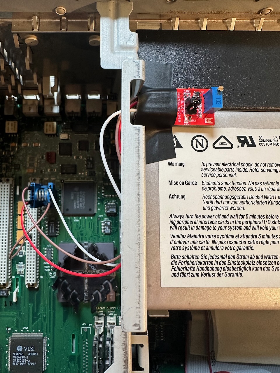
- To ensure things don’t flop around and cause shorts or disconnects, you’ll want to attach your Spicy to the case or board. I recommend attaching it to the top of the power supply which allows easy access. To do so:
- Apply electrical tape to the back of the Spicy to prevent shorts and allow for easy removal in the future.
- Apply double stick tape to the electrical tape.
- Thread the Spicy and it’s jumper wires through the hole in the metal bracket above the power supply.
- Remove the backing on the double stick tape and stick the Spicy onto the top of the power supply next to this hole. Do not place the Spicy any closer to the back of the case than this hole. There is insufficient vertical clearance beyond this point and closing the case will rip your Spicy off and potentially damage it.
- Now we’re ready to configure the Spicy:
- Set the jumper to the
SLsetting, per the manual. - Turn the screw on the variable oscillator clockwise 5-10 turns. At this point we have configured the machine to boot at or near the minimum Spicy speed, 35.7MHz.
- Set the jumper to the
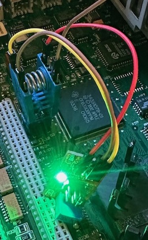
- Double check you have followed the instructions and verify all your voltages look good. Now you’re ready to power on the machine:
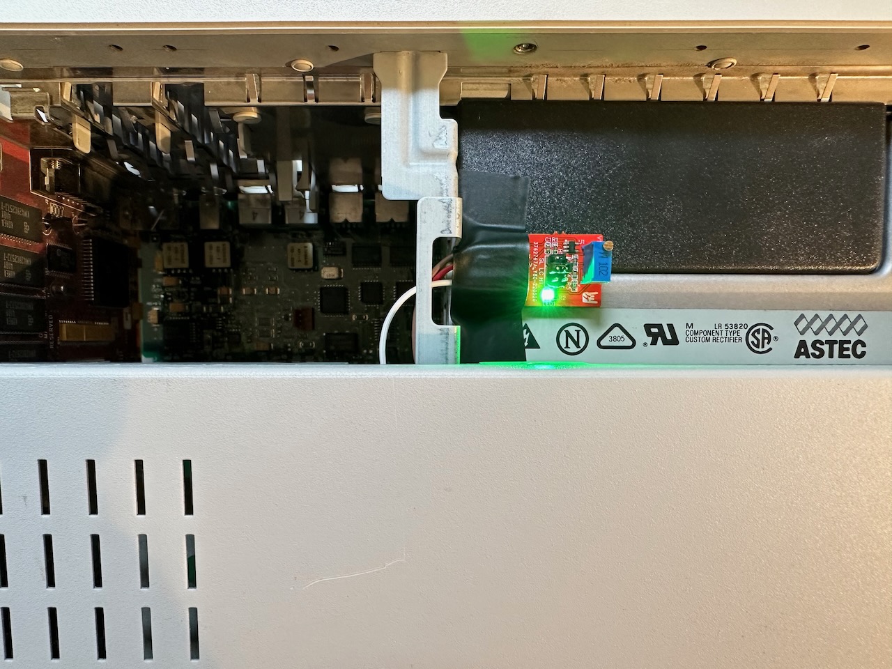
- Power on the machine.
- The Spicy should turn on it’s LED. This is a good sign, but does not mean everything is setup correctly. If it does not illuminate, power off your machine and check the connections.
- You should hear the normal boot chime. If it does not chime, power off your machine and check the connections. If the connections look good, turn the variable oscillator clockwise 5 more times to further reduce the clock speed.
- Allow the machine to boot.
- Use a tool like TattleTech or Clockometer to check the clock speed. If it is running at 35.7MHz or greater, your Spicy is correctly installed as a Spicy O’ Clip!
- Now you can fine-tune your overclock using the instructions in the Spicy O’ Clock manual.
- You can easily adjust the overclock by sliding the case back a few inches to access the Spicy.
- You can easily adjust the overclock by sliding the case back a few inches to access the Spicy.
If everything looks good, enjoy your new super-fast machine!
To disable the Spicy, it’s usually sufficient to remove the OE wire connected to ground. However, if this is insufficient or you want to completely remove the board, simply remove the clip from the logic board’s oscillator.